Sunday, July 21, 2013

Connecting the Connecting Rods

Previously, the bores in the old connecting rods were shown with some pretty significant scoring from the wrist pins. So far, every other lubricated surface in the engine looked pretty decent so I wonder if this part wasn't getting enough oil? Hopefully that will not continue.

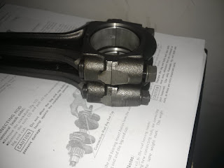
Here's the rods getting pulled apart. With just the socket wrench, it took just about all I had strength wise. Then I added the cheater pipe and they came off with barely an effort. Amazing what a little leverage can do. The last few pics just show that there was good lubrication in there and the rod bearings looked good.


Now here's something interesting. The manual shows that there are a few different color coded bearing inserts- black, brown and blue. The markings are supposed to be on the back side but darned if I see anything. I didn't notice any color markings on the replacement rod bearings either. Perhaps it wears off.


Another oddity is that the replacement rods do not have a weight stamp on them like they should. Mine are stamped with a "J". The two rod pieces are machined together and need to be paired together. The stamp helps to match the two pieces. I have no idea if the replacement rods are matched correctly.  I'll just have to trust that they are.
 
*Update* I think the weight markings just wore off. Its not stamped, just ink. The "J" ink on my rods rub off easily. But I'm pretty sure I have the replacement rods on correctly. 


And now the new rods are on, torqued to spec. They seem to fit fine. I can only cross my fingers that the bearings are correct and the rods parts are paired up right.


Balancer Assembly

Time to get those balancer weights in the lower crankcase. The first pictures shows the parts except the chain- weights, shafts, bunch of washers, and 2 little bolts that anchor the weights to the shafts.
The next picture shows it in place with the chain. The only tricky part was keeping all those washers in place next to the weights while at the same time sliding the shaft through the center.
The next picture show how different color links must be positioned over punch marks in the weights. I don't know why this must be so, but I have a feeling I'll find out soon enough.

Thursday, July 18, 2013

Replacing Parts Part II

Here are my "new" replacement rods from Mr. C's Motorcycles in Appleton, WI! Mr. C has tons of metric parts so check out their ebay store. I had no clue they were so close (just 30 miles away) until I noticed their address on ebay while selecting the shipping options. I picked them up right from their warehouse. Notice the difference? These rods are in much better shape- nice smooth bores.


These are the "new" balancer chain slippers ordered off ebay which also are in better shape.


I forgot to post some before and after engine cleaning pictures before I took the long break from this project so here you go! It was a combination of old fashion elbow grease and glass bead blasting. My homemade blasting cabinet was a little too small so I did some of it in my back yard. After glass beading, I went nuts with a pressure washer to clean out the beads. You don't want that stuff inside your engine. When pressure washing, some small parts like washers and o-rings started flying out from who knows where. Luckily, I retrieved them all and have now figured out where they came from. She cleaned up pretty good, no?


Wednesday, July 17, 2013

Next Project?

Viragos are ugly. But this is one of the best cafe racers I've ever seen. I'm not a big fan of cafe racers either, yet I LOVE THIS BIKE!

What an amazing transformation. Its old school but also has a futuristic look to it. Just beautiful.

My next poject is a long way off, but this is near the top. Viragos can be had cheap too.

Replacing Parts

So previously I mentioned a missing dowel pin. Here's a picture of a new one I ordered (hand model courtesy of ebay seller). No wonder it went missing.
 
 
And that pin goes underneath the star shape part below to keep it from freely spinning. The manual calls the star shape "Operating Plate" but the parts catalog calls it "Cam-Change Drum". Below this cam-change drum is a positioning pin that, with the help of a spring, locks the cam-change drum into place as it rotates with the rest of the shift drum assembly. So basically when you shift, the pin helps the shift drum assembly "snap" into 1st, 2nd, 3rd, 4th and 5th gears. If you look close, you can see the track marks running along center from the pin. That's my theory anyway. 
 
 
The snap ring (or circlip) next to the cam-change drum was put in place with the Harbor Freight snap ring pliers below. I didn't have this tool during disassembly and bent a bunch of rings. I had to order several new ones. Yes, I should of had this tool from the beginning.
 
 
Here's some worn out balancer chain slippers (or guides). The kz750 twin has counter weights in the crankcase that counteract the piston and crankshaft vibration. The balancer chain rotates two weights. I'm replacing these chain slippers. 


Way back I had serious problems with a piston pin. It wouldn't come out without heat and a lot of force (which ended up chipping the piston). Here you can see scratching and scoring on the stuck pin and in the connecting rod. I wonder what caused this to happen?


This is the other rod. Much better but still some scoring on the edge. Needless to say, the pins and rods are being replaced.


Sunday, July 7, 2013

Everything Now in Reverse.

So finally I'm getting to the rebuild in the phrase "engine rebuild". Everything before was teardown, dismantle, take apart and unscrew. The first two are quick shots of the bare lower crankcase and a gear shaft. The first step was to just look at all the case parts and get reacquainted with them. They sat in baggies so long I forgot what was what. After a few days of looking at the parts diagrams and laying it all out on my workbench, I felt confident enough to start actually placing parts back into the crankcase.

The 3rd pic is the first part to actually be reassembled! The shift drum I believe. With this I learned a valuable lesson. Follow those parts diagrams with extreme precision. I noticed right away that a circlip was missing. But not until a few days later did I realize almost by chance that another part was missing from the shift drum assembly- a little 4mm x 6mm dowel pin. Yikes. How many more little parts like that can I miss? Anyhow, those are now on order.

The shop manual is a mess, in my opinion. The reassembly steps are spread out all over. There is not a separate section devoted it. Instead, its tacked on at the end of each part's dismantling instructions. It creates constant flipping back and forth with no clear start or end point.

The last pic is a complete gasket set from Vesrah orded off ebay. I've read these are better quality than Athena.